More Info

Multi-Gang Reefer Outlet Installer Guidelines (PDF)
WARNING: Hazardous voltages in electrical equipment can cause severe personal injury or death. Inspection and maintenance should only be performed on this equipment after power has been turned off, disconnected, and electrically isolated so that no accidental contact can be made with energized parts.
Installation, operation, and maintenance of this equipment should be conducted only by qualified personnel.
Installation Instructions
• Installation should comply with drawings, manufacturer’s written instructions, and all local and national codes (e.g. NEC).
• Use only Listed hubs and fittings for all entries.
• Care should be exercised to ensure that the types and temperature ratings of conductors being installed in the unit are suitable for use with the terminals provided.
• Use care in stripping insulation from conductors so as not to nick any of the conductors. For aluminum, clean all oxide from the stripped portion and apply an anti-oxide compound.
• Check and tighten all accessible electrical connections to the manufacturer’s torque specifications. If such information is not provided with the equipment, consult ESL.
• Manually exercise all switches, circuit breakers, and other operating mechanisms to make certain they operate freely.
• Check to determine that all grounding connections are properly made.
• To make sure that the system is free from short circuits and ground faults, conduct an insulation resistance test phase to ground and phase to phase with the switches or circuit breakers in both the open and closed positions. If the resistance reads less than 1 megohm while testing with the branch circuit devices in the open position, the system may be unsafe and should be investigated. If after investigation and possible correction, low readings are still observed, ESL should be contacted. Some electronic equipment (metering, TVSS, etc.) may be damaged by this testing. Refer to the manufacturer’s equipment markings for guidelines.
• Clean the enclosure of all foreign materials. If parts at connection points are spattered with cement, plaster, paint, or other foreign material, remove the foreign materials with great care to avoid damage to the connections.
• After all conduits, wiring and terminations are complete, all incoming conduits must be sealed to prevent moisture intrusion from the conduit. A UL Listed or Classified expanding foam sealant (such as Handi-Foam® Expanding Sealant), or other sealing product meeting local codes and/or NEC requirements shall be used. The product selected must be able to permanently seal around all wires and the conduit (common ‘Duct Seal’ is not acceptable for this application). The sealing shall be done at the entry into the enclosure so the seal can be verified and inspected by removal of the access cover. Failure to seal may allow condensation and will void warranty.
• Set any adjustable time current trip device settings to the proper values.
NOTE—Experience has indicated that damage from overcurrent can be reduced if the devices used for overload and short-circuit protection are set to operate instantaneously (that is, without intentional time delay) at 115 percent of the highest value of phase current which is likely to occur as the result of any anticipated motor starting or welding currents.
• Install covers, close doors, and make certain that no conductors are pinched and that all enclosure parts are properly aligned and tightened.
• Qualified personnel should be present when the equipment is energized for the first time. If short circuit conditions caused by damage or poor installation practices have not been detected, serious personal injury and damage can occur when the power is turned on.
Initial Energization
Qualified personnel should be present when the equipment is energized for the first time. If short circuit conditions caused by damage or poor installation practices have not been detected, serious personal injury and damage can occur when the power is turned on.
The equipment should be energized in sequence by starting at the source end of the system and working towards the load end. In other words, energize the main devices, then the feeder devices, and then the branch-circuit devices. Turn the devices on with a firm positive motion.
Description and Operating Instructions
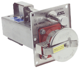
The Modular Interlocked Power Outlet, or ‘Module’ is ESL’s premier product. Our modular design allows quick field replacement of inoperable units which facilitates convenient servicing of the power outlet and contacts, minimizing downtime and maximizing the availability of revenue producing reefer outlets. The ESL interlock design offers the best combination of operator safety and functional simplicity, key features include:
• Socket remains de-energized until a reefer plug is properly mated and the on/off rod is engaged.
• Socket is de-energized manually with the operating rod or automatically if the plug is withdrawn.
• Branch circuit and equipment protection is provided by a UL listed, molded case circuit breaker, designed to clear multiple high ampere faults.
• Receptacle is designed to minimize arc-tracking, moisture sensitivity and replacement time.

To Operate the Unit:


CAUTION: Always inspect electrical connectors prior to use. If either side of the connection exhibits excessive wear, contamination, evidence of tampering, damage or other questionable features have the suspect components inspected by a qualified electrician before use.
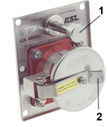
Open snap cover (2).
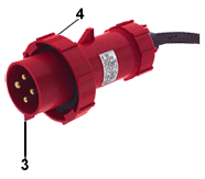
1. Insert plug into receptacle aligning the key on the plug (3) with the mating groove in the receptacle. For plugs with a less distinguishable polarization feature, note location of ground pin in plug which is a different size than the other 3 pins (for 30A, 32A & 50A plugs ground pin is larger, on 60A plugs it is smaller). Align plug ground pin with receptacle ground sleeve.
2. Fully engage plug in the receptacle, then engage and secure lock ring (4) until snug. (1/4 turn for 32A, multiple turns for others)
3. To energize, PUSH On/Off rod (1) fully to the ON position (unit may need to be reset).
4. To de-energize, PULL On/Off rod (1) out fully to OFF position.
5. To reset a tripped breaker, PULL On/Off rod to Off /RESET position, then PUSH to ON position.
Maintenance Information
WARNING: Hazardous voltages in electrical equipment can cause severe personal injury or death. Inspection and maintenance should only be performed on this equipment after power has been turned off, disconnected, and electrically isolated so that no accidental contact can be made with energized parts.
Installation, operation, and maintenance of this equipment should be conducted only by qualified personnel.
Maintenance
• Inspect the unit once each year, or after any severe short circuit.
• If there is an accumulation of dust and dirt, clean out the unit by using a brush, vacuum cleaner, or clean lint-free rags. Avoid blowing dust into circuit breakers or other components. Do not use a blower or compressed air.
• Carefully inspect all visible electrical joints and terminals in the bus and wiring system. Check and re-tighten all accessible electrical connections to the manufacturer’s torque specifications. If such information is not provided with the equipment, consult ESL.
• Carefully inspect all receptacles. Remove any dust and/or dirt by wiping out with a clean lint free rag. Inspect for any cracks or breakage. If any are found, replace the component. Inspect the pins and/or contact sleeves. Look for signs of heating (discoloration) or arcing (pitting). If any are found, replace the receptacle.
• Check that all receptacle covers properly close and seal against the face of the receptacle.
• Visually check all conductors and connections to be certain that they are clean and secure. Loose and/or contaminated connections increase electrical resistance which can cause overheating. Such overheating is indicated by discoloration or flaking of insulation and/or metal parts. Pitting or melting of connecting surfaces is a sign of arcing due to a loose, or otherwise poor connection. Parts which show evidence of overheating or looseness should be cleaned and re-torqued or replaced if damaged. Tighten bolts and nuts at bus joints to manufacturer’s torque specifications.
• Examine any circuit breaker surfaces for the presence of dust, dirt, soot, grease, or moisture. If such contamination is found, the surfaces should be cleaned.
• Examine any circuit breaker’s molded case for cracks. The integrity of the molded case is important in withstanding the stresses imposed during short circuit interruptions. Breakers should be replaced if cracks are found.
• Operate each switch or circuit breaker several times to ensure that all mechanisms are free and in proper working order. Replace as required.
• Do not oil or grease parts of molded case circuit breakers.
• Exercise switch operating mechanisms and external operators for circuit breakers to determine that they operate freely to their full on and off positions.
• Check the integrity of all electrical and mechanical interlocks and padlocking mechanisms.
• Test lamps for proper operation. If the lamps are in a marine environment it is recommended that lamps be replaced every two years.
• Seal off any conduits which have dripped condensate, and provide means for further condensate to drain away from the unit.
• Desiccant should either be replaced or re-activated. The desiccant can be re-activated by heating in an oven to 245 – 275 °F for 12 hours.
